Transformers, Harmonic Currents
Harmonic currents are omnipresent in electrical distribution systems and can cause a variety of problems. It is therefore important to understand which solutions are available to us. In this article, we will review various ideas that will be useful for solving problems related to power quality.
Phase Shifting and Harmonics
The best way to eliminate harmonics is to use a technique known as “phase shifting.” The concept of phase shifting involves separating the electrical supply into several outputs; each output being phase shifted with the other outputs with an appropriate angle for the harmonics to be mitigated. The idea is to displace the harmonic currents in order to bring them to a 180° phase shift so that they cancel each other out.
Hence, an angular displacement of
- 60° is required between two three-phase outputs to cancel the 3rd harmonic currents
- 30° is required between two three-phase outputs to cancel the 5th and 7th harmonic currents
- 15° is required between two three-phase outputs to cancel the 11th and 13th harmonic currents
For instance, in the case of two variable-speed drives of similar ratings, installing a Delta Wye transformer (30° phase shift with respect to the primary) on one drive and a delta-delta transformer (0° phase shift with respect to the primary) on the other drive gives an angular displacement of 30° between the two outputs. On the common primary supply of both transformers, phase shifting between the systems will cancel the 5th and 7th harmonic currents.
The above approach, i.e. phase-shifting non-linear loadsis used to reduce the effects of certain harmonics.
Current Harmonics, Voltage Distortion and Transformers
The mathematical equation V = RI shows that any current flowing within a resistance (impedance) generates voltage at the terminals. This equation also applies to harmonic currents flowing through the electrical system. The higher the harmonic current levels, the greater the resulting harmonic voltages; thus creating distortion in the electrical system voltage. As transformers also have impedance, voltage distortion appears at the transformer’s secondary terminals when harmonic currents flow through it.
Therefore, to reduce voltage distortion two factors can be modified: the level of harmonic currents and transformer impedance.
Phase-Shifting Transformers Designed for Non-Linear Loads
The level of harmonic currents may be reduced using phase-shifting transformers. Impedance plays a crucial role in reducing voltage distortion.
Phase-shifting transformers allow the treatment of harmonic currents through cancellation. Moreover, these transformers are designed to withstand the additional overheating caused by harmonic currents. The quality and reliability of the electrical system can be improved considerably by using harmonic mitigating transformers.
Below are a few examples of such transformers along with a description of their respective use.
Harmonic Mitigating Transformer
(Using 0° or -30° primary-secondary angular displacement)
The primary of the transformer has a delta connection and the secondary has a special double winding connection. Although there is only one secondary three-phase output, the electromagnetic effect of its secondary winding with a zigzag connection ends up cancelling the 3rd , 9th and 15th harmonic currents. Features of the Harmonic Mitigating Transformers include:
- A capacity for handling nonlinear loads.
- Cancellation of the 3rd , 9th and 15th harmonic currents in the zigzag-connected secondary of the transformer.
- A reduction in voltage distortion (3rd harmonic voltage reduced by low zero-sequence impedance).
When two transformers with a delta-zigzag connection (-30° and 0°) are used for phase-shifting, the 3rd harmonic currents are cancelled in the secondary windings. The 5th and 7th harmonic currents are cancelled in the electrical supply common (Point of Common Coupling) to both transformers and the voltage distortion is reduced.
If a single delta-zigzag transformer (0°) is used in a system made up of Delta Wye transformers (-30°), the 5th and 7th harmonic currents originating from the delta-zigzag transformer (0°) will attempt to cancel the 5th and 7th harmonic currents originating from the Delta Wye transformer (-30°) already present. This reduces the 5th and 7th harmonics in the system.
Dual-Output Harmonic Mitigating Transformer
(Using 0° and -30° primary-secondary angular displacement)
The primary of the transformer has a delta connection and its secondary has a Dual-output winding connection with two coils each rated at half of the total kAV. Although there is only a 30° angular displacement, the electromagnetic effect of its dual secondary windings with a zigzag connection ends up canceling the 3rd , 5th, 7th, 9th and 15th harmonic currents. This means a dual-output HMT is effective at canceling harmonics from both single and three phase non-linear loads. Features of the Dual-Output Harmonic Mitigating Transformer include:
- A capacity for handling non-linear loads.
- Low-impedance cancellation of the 3rd , 9th and 15th harmonic currents (zigzag-connected secondary).
- Cancellation of the 5th and 7th harmonic currents (30° phase shift between the outputs).
- A reduction in voltage distortion (3rd harmonic voltage reduced by low zero-sequence impedance
Power Factor and Harmonics
The power factor is the ratio between the active power (W) and the apparent power (VA). Electricity supplied by Utilities has a sinusoidal voltage wave of 60 Hz. If the current and voltage curves are not aligned, the efficiency of the electrical system is diminished and the apparent power exceeds the active power. In an inductive system, the voltage curve leads the current curve. In a capacitive system, the current curve leads the voltage curve. In general, when speaking of the power factor, we are actually referring to the displacement factor.
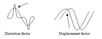
For the past few years, because of the increase in nonlinear loads, we have had to take into account the effect of harmonics in electrical systems and modify certain mathematical equations. The power factor is now defined as:
PFtot = Fd * Fdist
Where PFtot = total power factor
Fd = displacement factor (as defined above)
Fdist = distortion factor = fundamental current / RMS current
A new term has therefore been added, the “distortion factor”, which is defined as being the fundamental current divided by the RMS current (current measured with a true RMS clamp-on ammeter).
There are two elements that combine to deteriorate the power factor; inductive or capacitive loads. These affect the displacement factor and the harmonic currents of the non-linear loads, which affects the distortion factor. Reducing the level of harmonic currents in a system therefore improves the systems power factor.
As the utilities measure the total power factor, we will have to check the value of these two factors if it is to be corrected. The good news is that companies that manufacture measuring instruments now provide the value of both of these factors. This will help us understand the cause of the deterioration of the power factor and choose the best way to improve it.
Capacitors
Capacitors are commonly used as harmonic current filters or to correct the power factor in industrial electrical installations. For instance, if a system has not been properly calculated or if certain modifications were made without taking existing parameters into account, capacitive impedance nears the inductive impedance of the load at a certain harmonic frequency and creates resonance in the system. Major voltage spikes and distortions will then occur in the system, damaging sensitive electrical equipment and shortening the capacitors’ lifespan. It is thus very important to consult electrical system experts when applying this technology.
Case Study
The power supply of four computer rooms at Algonquin College is divided between two distribution panels.
Power measurements were taken while a 75kVA low Z transformer was installed to supply the two panels. These readings are shown in Table 1 (next page).
This transformer was replaced with another one with the same power rating whose primary winding was delta-connected and whose secondary winding was dual-output special winding connected, with an angular displacement of 30° between the two outputs, with each output supplying one of the panels. New power measurements were takenand are shown in Table 2.
Since the measurements were made at different times and the number of computer stations in operation was different, there was a slight variation in power measurements between the two tables.
Comparing the two tables, one can see that the dual-output zigzag transformer helps to improve the power factor and greatly reduces the level of harmonic currents injected into the electrical system. The power factor of a computer load is shown in Table 1 and Table 2 .685 to .746. If a phase shifting transformer is used, the difference on the primary side is from .882 to .982.
TABLE 1
|
Low impedance transformer |
Primary | Panel #1 | Panel #2 | ||||||
| A | B | C | A | B | C | A | B | C | |
| Voltage (Volt) | 573 | 571 | 574 | 199 | 199 | 199 | 198 | 198 | 198 |
| Power (kW) | 14.5 | 7.62 | 6.53 | ||||||
| Apparent power (kVA) | 16 | 11 | 9.3 | ||||||
| PFtot | .882 | .72 | .707 | ||||||
| THDv (%) | 2 | 1.9 | 1.6 | 2.6 | 3.9 | 4.2 | 2.8 | 3.9 | 4.3 |
| THDi (%) | 55 | 50 | 52 | 33.7 | 88.2 | 58.1 | 98.6 | 13.4 | 99.5 |
| THDv (%) 3rd harmonic | .3 | .5 | .5 | 1.3 | 2.4 | 2.4 | 1.2 | 2.6 | 2.2 |
| THDv (%) 5th harmonic | 2 | 1.6 | 1.3 | 1.9 | 2.6 | 3 | 2.2 | 2.5 | 3.2 |
| THDv (%) 7th harmonic | .2 | .4 | .1 | .7 | 1 | 1.1 | .8 | .9 | 1 |
| THDi (%) 3rd harmonic | 7.7 | 10.7 | 5.4 | 79.5 | 72.2 | 80.6 | 81.4 | 81.5 | 82.5 |
| THDi (%) 5th harmonic | 51.5 | 43.5 | 47.4 | 45.3 | 45.5 | 46.5 | 50.5 | 48.5 | 49.8 |
| THDi (%) 7th harmonic | 17.3 | 21.2 | 18.6 | 14.4 | 19.2 | 17.8 | 21.9 | 18.6 | 22.6 |
TABLE 2
| Double-output zigzag-connected transformer | Primary | Panel #1 | Panel #2 | ||||||
| A | B | C | A | B | C | A | B | C | |
| Voltage (Volt) | 570 | 570 | 571 | 197 | 197 | 198 | 198 | 198 | 198 |
| Power (kW) | 19.1 | 8.4 | 9.7 | ||||||
| Apparent power (kVA) | 19.4 | 12.3 | 13 | ||||||
| PFtot | .986 | .685 | .746 | ||||||
| THDv (%) | 2.5 | 2.4 | 2.5 | 2.8 | 2.6 | 2.9 | 4.6 | 4.7 | 4.7 |
| THDi (%) | 19.6 | 18.4 | 18 | 39.7 | 72.4 | 34 | 57.6 | 14.7 | 59.4 |
| THDv (%) 3rd harmonic | .3 | .3 | .3 | .5 | .6 | .2 | .5 | .7 | .1 |
| THDv (%) 5th harmonic | 2.3 | 2.1 | 2.3 | 1.9 | 1.6 | 1.7 | 4.1 | 4.4 | 4.3 |
| THDv (%) 7th harmonic | .5 | .3 | .5 | 1.6 | 1.6 | 2 | .5 | .6 | .7 |
| THDi (%) 3rd harmonic | 4.2 | 6.3 | 3.8 | 85.8 | 77.5 | 82.8 | 73.1 | 74.1 | 75.7 |
| THDi (%) 5th harmonic | 11.6 | 10.7 | 8.2 | 61 | 56.5 | 58.9 | 38.6 | 40 | 44.6 |
| THDi (%) 7th harmonic | 14 | 12.8 | 14.8 | 33.5 | 33.4 | 32.3 | 9.8 | 11.1 | 15.5 |
Conclusion
A thorough understanding of electrical system-related problems will help us implement better solutions. It is estimated that over 70% of electrical loads are now non-linear. Non-linear loads will continue to increase due to the proliferation of new technologies such a Electrical Vehicle Charging. The deterioration of the power factor will often be caused by harmonic currents (distortion factor) and not by inductive loads (displacement factor).
While not discussed in this paper, the combination of harmonic mitigating transformers, line reactors and drive isolation transformers provides the easiest and most economical method to correct power quality issues within a system. As a proven final solution, Active Harmonic Filters (AHF’s) can be deployed to correct any remaining harmonic issues to guarantee a facility will meet standards such as IEEE-519 2014.
To find a proper technique for correcting the power factor and reduce harmonic currents in our system, the following must be considered:
- Determine the components of the total power factor.
- Correct the displacement factor at the inductive source (by adding capacitors).
- Correct the distortion factor at the harmonic source by reducing harmonic currents and phase shifting systems.