Simulate a 12-Pulse VFD Using Two 6-Pulse VFD’s
Many variable frequency drive (VFD) manufactures currently offer 18-pulse VFD’s that meet IEEE-519 THDi if the point of common coupling (PCC) is defined as the VFD itself. Using a method that gives slightly lower cancellation called 12-pulse can aid in meeting IEEE-519 when the PCC is defined as the more traditional utility service entrance. Users can use two standard 6-pulse VFD on either a dedicated 12-pulse transformer or duplicate this effect by combining standard delta-wye drive isolation transformers with delta-delta or delta-zig/zag (0o) on alternate VFD’s. By using two transformers, the delta-wye transformer phase-shifts the VFD’s power supply phase angle by 30o. This has the effect of phase-shifting that VFD’s harmonics and through summation with the second zero degree (0o) connected transformer, most of the 5th, 7th, 17th and 19th harmonics are cancelled out provided the two VFD’s have equivalent loads. A dedicated 12-pulse transformer has two secondary windings that have the same effect as using a delta-delta/delta-zig/zag and delta-wye transformer with two VFD’s. Several factors need to be taken into account when using two or more VFD’s to simulate a 12-pulse application for proper THD mitigation.
1. The VFD’s should be the same manufacturer and model. VFD’s from different manufactures and models may have slightly different harmonic levels at a given frequency and load. A 12-pulse application must have equivalent harmonic frequencies and levels for the harmonics to cancel out.
2. The VFD’s should be of equal size and ideally share similar loads. An application where the loads vary widely between the two VFD’s on the 12-pulse circuit may not cancel harmonic current effectively.
3. When separate delta-delta and delta-wye/delta-zig-zag transformers are used, they need equivalent impedances. The application and need for equivalent impedances should be specified during the quotation process. If matching an existing transformer, its impedance should also be specified. It is important that the secondary voltages are equal and their impedances remain equivalent at a given load.
4. If you are using two transformers, they must be located in close proximity. Preferably, there should be equivalent distances in cable length and size between the VFD’s and transformer(s) and between the two transformers and the PCC. Having equal distances between the VFD’s and transformer(s) is also true if you are using a dedicated 12-pulse transformer. Harmonics do not propagate through an electrical system linearly and common cable lengths help match the harmonics produced by each VFD.
Failure to properly follow the suggestions above can cause your 12-pulse application to be less effective than it could be. Hammond Power Solutions can supply a complete line of low and medium voltage 12-pulse or delta-delta/delta-zig/zag/delta-wye transformers for your application.
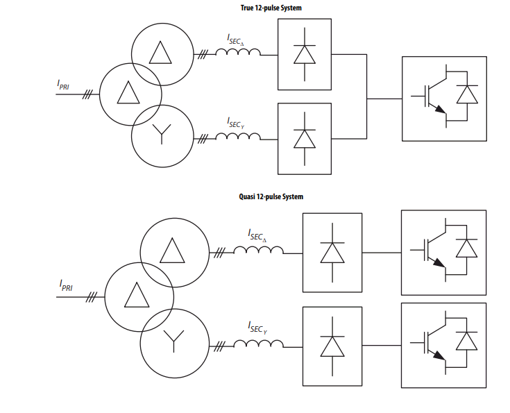
Figure 10: Rockwell’s Application Guidelines for 12-Pulse Operation
of PowerFlex 750-Series AC Drives
For additional information see:
https://literature.rockwellautomation.com/idc/groups/literature/documents/at/750-at003_-en-p.pdf